Visual Beep
The quieter you become, the more you hear.
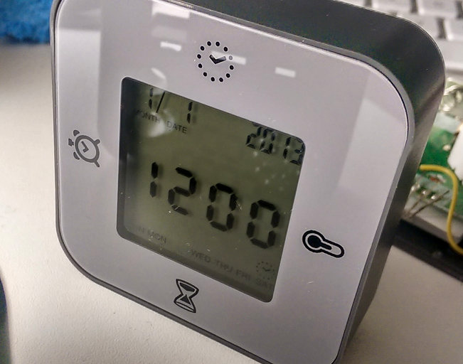
I was hanging in the local IKEA store when I came across this $5 multifunction digital clock. The interesting thing about it is that you switch between the functions, not by pressing a button, but by turning the clock on its various sides. It has four sides and hence four functions: thermometer, alarm, clock and countdown timer. The countdown timer in particular is awesome. You set the timer and every time you turn the clock on the timer side, it automatically starts counting down.

It comes under two names: LÖTTORP and KLOCKIS
So far so good except one little annoyance: the beeping. I prefer visual notification over sound — top reasons being:
- It’s directional and thus easily ignorable (ie turn your head away).
- It can be noticed even if I have headphones on.
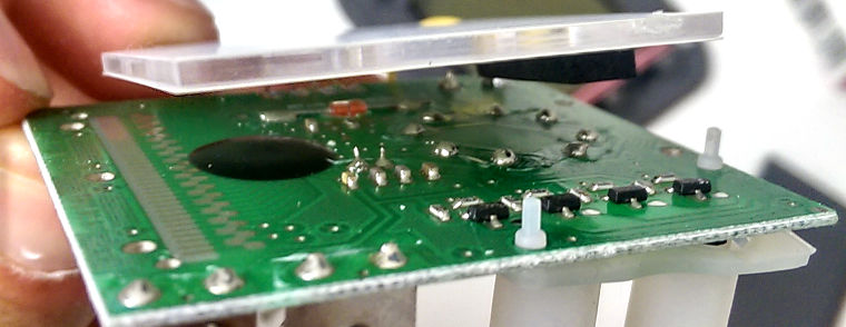
Given that the clock has a backlight, I thought why not hook the buzzer straight up to the backlight. And that’s what I did. The only hiccup was figuring out how to disassemble it. I went with sheer brute force and broke all four screw holes. After the fact, I found out that the front glued panel was hiding the holes.
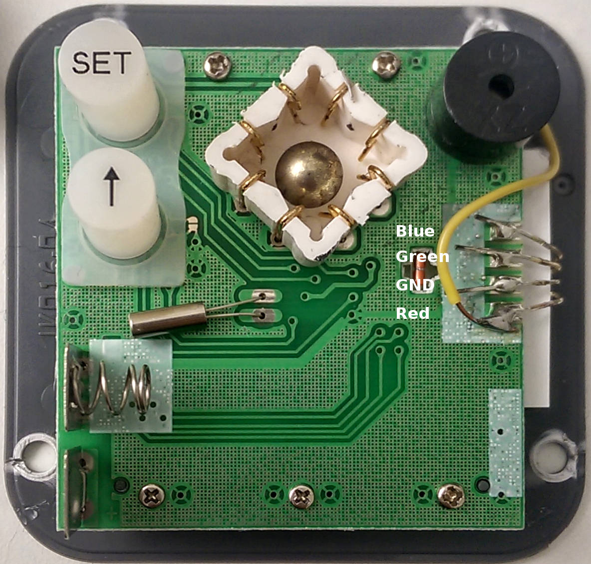
Above photo shows the opened backside of the clock. There are three interesting things here:
- The severed screw holes, courtesy of sheer force of a screw driver used as a lever.
- The yellow wire connecting the positive terminal of the buzzer to anode of the red LED.
- and finally, the elephant in the room: big steel ball inside the white box. Apparently it is cheaper to make this mechanical abomination than using an accelerometer. Having said that, given that the same thing is used in Dyson’s Hot+Cool heater as a safety mechanism that cuts the power when the heater falls on its side, there may be a reliability reason behind using this instead of an accelerometer. For the uninitiated, this is the part that lets the clock computer know which side is up. The steel ball connects different pairs of wires on the corners of the box depending on which side the clock is sitting on.
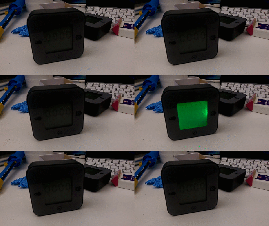
I later removed the buzzer and hooked the buzzer terminal to the green light since green light is more noticeable. Duct tape replaced screws and you can see the final effect in the video at the end of this post.
I can think of an improvement to this hack whereby instead of using a simple wire, a diode is used to prevent current flow back to the speaker driver when the LED is switched on by the processor. A resistor in series would also be a good idea to limit the current draw by the LED. Note however that the diode will cause a voltage drop which combined with the LED in series may be higher than the supply voltage and therefore not enough to turn the LED on.

The rest of the electronics is fairly boring and the computer chip is one of those black blobs you find in Casio calculators.

Try hearing with your eyes!
