A Control Panel for Electronics Prototypes
Every prototype needing human input starts with the same chore: wire loose buttons, LEDs and a potentiometer before testing the interesting part. So I made that recurring mess permanent.
This scrap-built, 3D-printed panel has four momentary buttons, two toggles, one potentiometer and three LEDs. Ten controls and indicators connect to any microcontroller through ordinary jumper wires. It is a reusable physical interface I can bring to a prototype instead of rebuilding inside it.
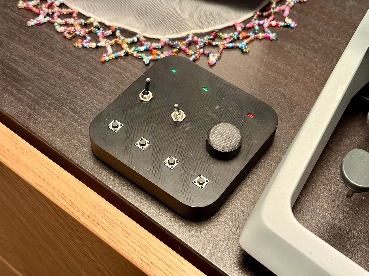
The first version: entirely scrap-bin electronics in a printed shell.
What is connected
One side of every button and toggle connects to common ground; the other reaches a front header. With a microcontroller’s pull-up enabled, closing a control pulls its input low.
The potentiometer exposes ground, its wiper and its other end, letting the prototype choose the voltage across the track and feed the wiper to an analogue input.
Each LED’s anode takes power from VIN while a MOSFET switches its cathode to ground. The microcontroller drives only the MOSFET gate rather than supplying LED current through a potentially weak GPIO pin. Current limiting must still suit the LEDs and VIN.
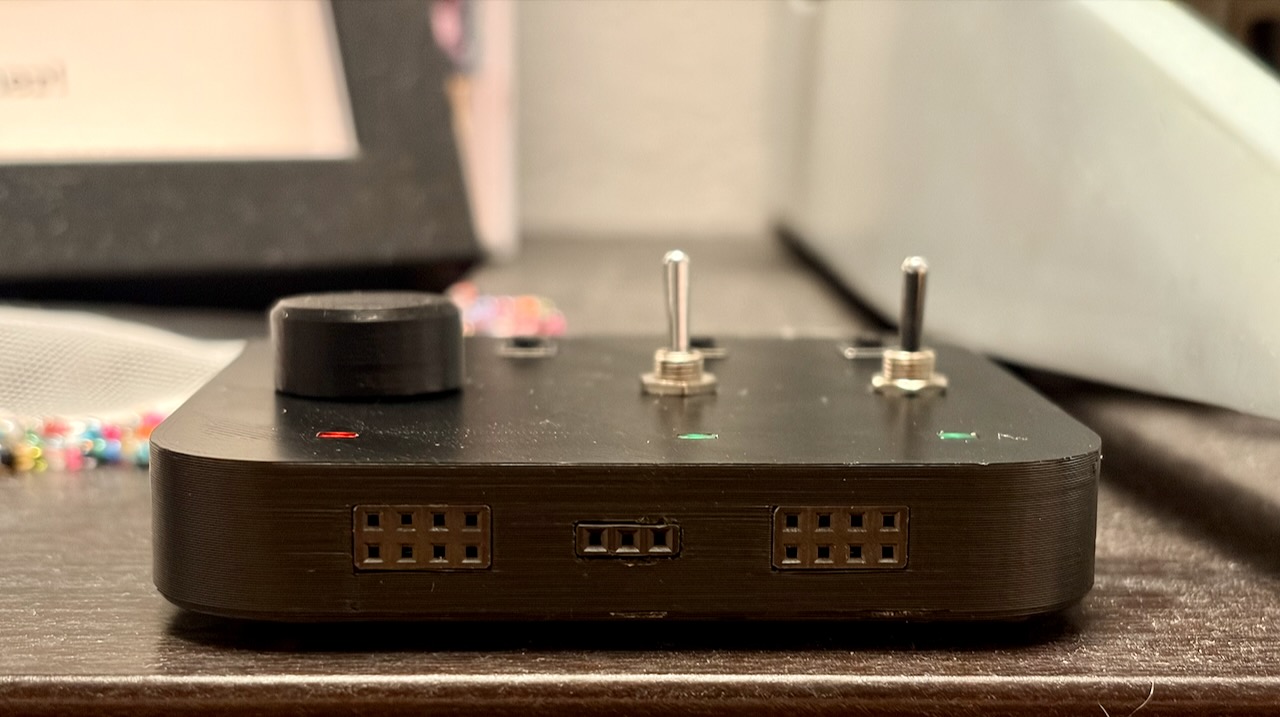
The female headers sit flush with the front face and accept ordinary jumper wires.
Why a separate panel
These are simple circuits, but rebuilding them consumes breadboard space, jumper wires and attention. Loose controls also make interaction testing needlessly awkward, and every rebuild creates another chance to debug wiring that has nothing to do with the prototype.
I found large switch consoles and boards for individual controls, but little in the useful middle: fewer than a dozen mixed controls in a small, microcontroller-agnostic package. This panel is bench infrastructure, not part of the product under test.
The next version
What I plan to add:
- Expose both ends of every button and toggle.
- Add selectable pull-up/down behaviour and debounced outputs.
- Regulate LED power for a wider VIN range.
- Make the PCB structural, possibly replacing the case entirely. It is a maker tool; the board does not need to hide.
- Make it prettier and add a writable labelling area.
- A magnetic base.
- Mechanical-keyboard-style buttons.
- Wireless control after the physical interface is right.
What I plan to leave out:
- LCD, e-ink and other displays.
- Joysticks.
Displays and joysticks would turn this into another development board. The aim is to make common physical controls instant, not to add protocols, software and application-specific behaviour.
Design Philosophy
I surveyed projects on the web, estimated the 90th-percentile count for each ordinary control and took roughly half. I then adjusted the numbers for a pleasant arrangement and removed specialty inputs. This was an informal guard against feature creep, not a scientific measurement: enough for common projects, without designing for every outlier.
Placement follows the hand. Frequently used buttons sit at the bottom, clear of everything else. The taller, less-used toggles and potentiometer occupy the middle, reducing accidental knocks. LEDs sit at the top, above the working hand, where they remain visible.
The flat case has conic, continuously curved corners—a simple, pleasant shape without the harsh curvature changes of ordinary rounded rectangles, like a squircle. Flat sides allow compact storage or standing on an edge; flush headers keep the front equally clean.